Pi header
Pins in use, coloured by the jumper on them in the photos. Odd pins are the row nearer the board edge.
Net list
Every conductor in the model, grouped by circuit. Click a row to light it up in the 3D view.
Cables leaving the enclosure
Left to right along the gland strip at the floor of the backplate.
What this is
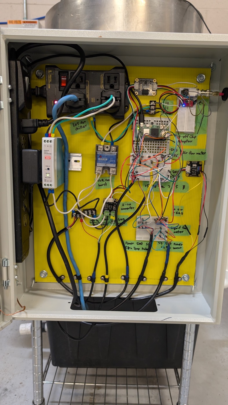
A steel enclosure on the front of a wire cart. The 100 L stainless fermentation vat stands on the floor behind it on a black base with a yellow rim, tall enough that its top shows above the box. Inside the box, a yellow corrugated backplate carries a Raspberry Pi Zero W that reads the vat's sensors and drives two actuators. Behind the vat, a narrow wire cart carries the air skid, the set of controls leading into the vat: filter-regulator, solenoid, proportional ball valve and hand valve, plus the PVC riser with a clear turbine flow meter that lifts liquid from the vat base back in at the top.
The Pi's job: hold the vat at a set temperature by switching the chiller, and give the vat timed gas bursts through the proportional valve, while logging pH, temperature, gas flow and liquid flow.
Power tree
- Mains 120 V enters a vertical power strip on the hinge side of the box.
- Strip → Digital Loggers IoT Relay IoT for chiller. Its normally ON outlet feeds the Mean Well 24 V supply. Its normally OFF outlet, switched by the Pi, feeds the chiller through the blue cord.
- Strip → 5 V USB adapter → Pi. The Pi's 3.3 V feeds the main breadboard rails −GND +3.3V; its 5 V feeds the sensor breadboard rails +5V −GND.
- Mean Well MDR-20-24 → 24 V bus → SSR load side (valve motor power) and the 18–24 V input of the 4–20 mA DAC.
Signal tree
- I²C (header pins 3, 5): 16-bit ADC, the 4–20 mA DAC 4-20 converter, and, through a galvanic isolator, the Atlas EZO-pH circuit.
- 1-Wire (GPIO 4, pin 7): stainless temperature probe with a 4.7 kΩ pull-up on the sensor breadboard.
- Pulse input (GPIO 22, pin 15): the clear hall-effect liquid flow meter on the PVC riser, level-shifted to 3.3 V.
- Analog: air flow meter on ADC A0.
- Outputs: GPIO 17 (pin 11) → IoT relay → chiller. GPIO 27 (pin 13) → SSR → 24 V to the proportional valve motor. The DAC's 4–20 mA loop sets how far that valve opens. Both GPIO lines land on the 13 / 11 terminal block first.
Air and liquid
- Gas: supply tube down the skid's left post → filter-regulator with gauge → up and over into the U.S. Solid proportional valve → NEW-LINE hand valve → blue tubing down the right post → air flow meter → brass tee and stainless line into the bottom of the vat. A second line tees off through the brass solenoid and a stainless riser to a shelf tee with a yellow-handled valve; where it goes next is not in the photos.
- Liquid: vat base → pump → PVC riser with the clear flow meter → red-handled PVC valves → back into the top of the vat. The chiller's coolant lines are not in the photos; the model runs them to the vat base.
Wire colours in the model
Mains hot / neutral white / earth green
Blue cord: switched mains to the chiller
24 V DC (+ white, − black), red to the valve
3.3 V and 5 V rails
I²C from the Pi: SDA purple, SCL teal; Gravity leads white or blue (SDA), green (SCL)
4–20 mA loop to the valve (green +, white COM)
1-Wire data
Analog / pulse sensor signal
Coax: pH probe to EZO circuit
Blue pneumatic tubing (air)
White PVC (liquid)
Boards, tape labels, valve legend and GPIO pin numbers are read from the photos. Inferred and marked as such in each part's notes: the exact breadboard jumper paths, the pump and chiller both running on the relay's switched outlet, the chiller's coolant lines, and the solenoid's wiring.
Readings
Vat temperature
--.-°C
1-Wire · GPIO 4
Air flow
0.0L/min
ADC A0 · 0.000 V
Liquid flow
0.0L/min
GPIO 22 · 0 Hz
Valve command
--.-mA
DAC over I²C · 0 % open
Gravity (model)
1.052
fermentation day 0.0
Outputs
| Pin | Signal | Drives | State |
|---|
| 11 | GPIO 17 | IoT relay → chiller + pump | low |
| 13 | GPIO 27 | SSR → 24 V valve motor | low |
| Indicator | Meaning | State |
|---|
| DLI power | Relay strip has mains | |
| MW DC OK | 24 V present | |
| Pi ACT | Pi running | |
| EZO blue | pH circuit in I²C mode | |
| Flow meter blue | Turbine sensor powered | |
Controls
Control loop in the model: the chiller switches on when the vat is 0.3 °C above setpoint and off 0.3 °C below it. Fermentation heat peaks around day 1.5 and the vat drifts toward a 22 °C room. Each burst powers the valve through the SSR for the set length; the DAC's 4–20 mA sets how far it opens. The pump shares the relay's switched outlet with the chiller in this model, so liquid flow reads only while the chiller runs.